AIRCRAFT CONSTRUCTION
An Article Series
by Ron Alexander
ELECTRICAL SYSTEMS SIMPLIFIED
Part 2
By Ron Alexander
Wiring your custom built aircraft is not an overwhelming task. It is a part of the building process that may appear to be staggering but when analyzed it is actually fairly simple. The problem encountered by several builders is the lack of information presented in many kit assembly manuals. Usually the basics are presented in the manuals but details are often omitted due to the varying requirements of each builder. Many individuals want to have a very simple electrical system with minimum equipment while others desire sophisticated avionics, electrical gear and flaps, etc. Because of this diversity, many kit manufacturers do not spend much time outlining the electrical system.
This article follows an earlier discussion in last month's issue on the basic knowledge you will need to wire your aircraft. This month I will detail the actual steps involved in installing your electrical system. Remember, all you are going to do is install the equipment you want in the desired location and then connect each component part to a power source. This narrows the installation process down to a very simple concept. You can make the wiring task as complicated as you like or you can keep it very basic and understandable.
The basic steps involved in wiring your amateur-built airplane are as follows:
- Determine what electrical equipment you are going to install
DETERMINING EQUIPMENT REQUIREMENTS
You may want a very simple electrical system with only a starter and alternator. On the other hand, you may be building an aircraft that requires a somewhat sophisticated system for maximum utilization of the aircraft design. The first step is to decide what electrical equipment you want to install on your aircraft and then calculate the current draw in amps each piece will require. Your aircraft may have electrical gear and flaps. You may want strobe lights, a starter, landing lights, cooling fans, electric elevator trim, etc. Decide now what to install then calculate the current draw of each item.
The current draw is often listed on the electrical component or it is available from the manufacturer. You will need to know the current draw in amps. This can be determined by using Ohm's law or, more commonly, the wattage will be given and you can then use the power formula expressed as Power = Voltage X Current. Using this formula we can then find the current draw in amps by dividing the watts by the voltage. This number will be needed later to determine the size of wire needed for the piece of equipment.
You should also decide if you are going to install a 14-volt system or a 28-volt system. The majority of custom-built aircraft will use a 14-volt electrical system. Of course, you want to ensure proper alternator output to power your electrical equipment. Additionally, begin to develop your schematic diagram at this point. Beginning a basic diagram at this time will make it easy to build on as you install the system.
LOCATE THE EQUIPMENT
It is very important to plan where you will place your electrical items. If you are planning to install strobes, landing lights, navigation lights, etc. you will want to route the wiring needed for both power and ground. In many aircraft designs, this must be completed during the early phase of assembly. Otherwise, you may find that you will be unable to route electrical wire or certainly find it to be a very difficult task. After locating equipment, route the necessary wiring being sure to identify each wire. You can identify each wire by using tape that is folded over and marked. The size of wire will be discussed in a later step. Use black wire for grounding of equipment so it is easily identified. Continue your schematic as you locate equipment.
LOCATE THE BATTERY, BUS BARS AND CIRCUIT BREAKER PANELS
Locate the battery as close to the engine starter as possible. This is desirable due to the high electrical draw the starter requires. The battery also must be protected from high temperatures and located in an accessible area for ease of servicing. Weight and balance will also be a consideration. Often a battery will be located in the aft portion of a fuselage to balance the aircraft. Be sure to properly vent the battery.
Recalling from the previous article on electrical systems - a bus bar is a central point where wires from electrical equipment are grouped together on a piece of metal (usually copper) and the metal bar is then connected to a power source. You may also have a grounding bus bar to locate in your aircraft. Several builders are using a central grounding point for all equipment rather than grounding to the fuselage frame. Composite and wood aircraft often use this type of grounding. Bus bars are usually located near the instrument panel for ease of installation. You will want them to be somewhat accessible but not exposed where they could cause injury.
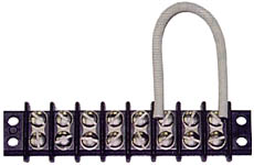
Terminal Strip
Circuit breaker/fuse panels are usually located in the cockpit area where they can be reached by the pilot during flight. This will normally be under an instrument panel or as a part of the instrument panel. Circuit breaker panels are also mounted on side panels. Often a bus bar will be used to connect circuit breakers together. This will allow the circuit breaker installation to serve as a bus bar. Circuit breakers can be grouped in a power bus by tapping holes in a copper strip and securing with small screws. Either terminal of the circuit breaker can be used to connect to the bus bar but you will probably find it more convenient to attach to the top terminal. The bus bar attaching the circuit breakers is then attached to a power source eliminating the need for a separate bus bar. You will probably want to fabricate more than one circuit breaker panel. These panels will then be located in different areas.
Aircraft builders often use fuse panels. A fuse bus bar is constructed using a heavy piece of copper wire and soldering the wire to the terminal of each fuse. This will also create a power bus. Most fuses require the use of soldered connections. Fuse panel installations will be cheaper than circuit breakers but you will have more difficulty changing a fuse in flight versus resetting a circuit breaker.
CALCULATE WIRE SIZE AND CIRCUIT BREAKER SIZE
Calculation of wire size will be necessary during the initial building phase. As discussed earlier, you will want to route electrical wires prior to completing the construction of the wings and fuselage. Proper wire size is critical to a safe electrical system. The match between the wire size and circuit breaker/fuse size is also critical. To determine the size of wire you will need, refer to FAA Advisory Circular 43-13. Two charts are presented; one displaying continuous flow and the other intermittent flow. What is the difference? Most aircraft electricians agree that any piece of equipment that operates more than 2-3 minutes at a time is considered continuous flow. That encompasses most items on an airframe. Intermittent flow then would obviously involve items that operate momentarily. An example of intermittent flow items is a landing gear or flaps. With that in mind, the builder enters the appropriate chart (intermittent or continuous) with the current draw of the equipment being connected to determine the proper wire size. The wire size is based upon the amount of current the wire will carry and the length of the wire.
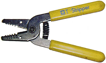
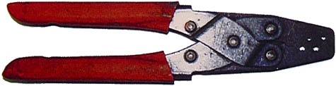
Wire strippers
Again, we are going to use Tefzel wire that is sold under military specification MIL-W-22759/16 for unshielded wire and MIL-C-27500 for unshielded wire. Resist the temptation to go to your local electronic store and purchase wire. Most of your installation will be completed using unshielded wire. Be sure to use good quality wire cutters and strippers to cut and prepare the wire. The same applies to the crimping tool you will need.
CONNECT EQUIPMENT TO POWER SOURCE
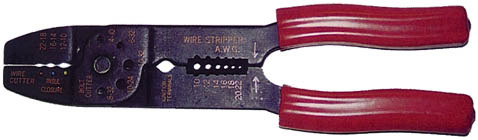
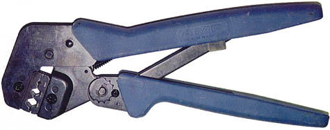
Crimping Tool
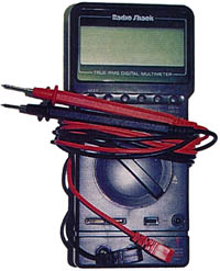
Care should be taken to properly connect all equipment to the power source. Most electrical problems encountered during the initial installation phase can be traced to a poor connection. Crimp on connectors must be carefully installed on a wire that has been properly cut. Cut about 3/16-inch of insulation away from the wire. Use a good quality crimping tool. The correct size connector should be used. The connectors are color-coded red for 18-22 gauge wire, blue for 14-16 gauge, and yellow for 10-12 gauge wire. Taking your time as you crimp each connector will save you hours of troubleshooting when you power up your system for the first time. Check the connection physically by pulling on the wire and connector. Protect the connection with the use of heat shrinkable tubing. This tubing will insulate the connection protecting it from electrical faults. Check each connection electrically using an ohmmeter. Equally as important are solder connections. Proper soldering techniques must be used. Practice your soldering before you attempt it on your aircraft.
Coax crimping tool
Routing of wires is also very important. After marking the wires you can group them into bundles. This is often very convenient when running several wires from one area to the bus bars. Several acceptable practices for routing of wire follows:
- Support wires and bundles of wires using MS21929 cushioned clamps.
- Do not allow bundles to have too much slack. Using normal hand pressure you should not be able to deflect the bundle more than one-half inch.
- Separate wires and bundles from flammable fluid lines. If this is not practical, always run the fluid lines below the wire bundle and separate the two by 6 inches or more.
- Protect wires in high temperature areas by using insulating sleeves.
- When running bundles or wires through cutout areas such as bulkheads, protect from chafing by using a rubber grommet.
- Splicing of wire is permitted but should only be used if necessary.
- No more than one splice per connection is recommended.
- The splice should not be within 12 inches of a terminal end.
- Be sure wires are at least 3 inches from control cables. If not possible, use a guard to prevent contact.
Proper routing of cables is necessary to prevent the wires from coming in contact with other parts of the airplane. This can easily occur as a result of movement or vibration. A wire can obstruct movement of a control or it can be damaged causing a short. A shorted wire can be very difficult to locate. This is one other reason to be very careful during the entire installation process.
GROUNDING AND BONDING
Grounding is defined as the electrical connection of a conducting object to the primary structure to provide a return path for the electrical current. Bonding is the electrical connecting of two or more conducting objects not otherwise connected. The difference between the two can be confusing. A simple explanation is that bonding may not always result in a ground. It may only connect objects. Metal aircraft have a built in ground - the airframe. The main frame of a metal aircraft can be used as a ground. Many builders will use a grounding strap and connect the piece of equipment to be grounded to the frame itself. Another method of grounding is to use a common grounding bus bar. This bar can be located under the instrument panel and used to connect all ground wires from equipment throughout the aircraft. This is referred to as a central grounding point. The grounding bus bar is grounded to the engine of the aircraft. In this case two wires must be run to each piece of equipment - the power wire and the ground wire. This type of grounding is more common in composite and wood aircraft. Both of these aircraft require some form of ground other than their airframe. Wood and composite material do not conduct electricity.
| Grounding block and pin connector may be used as a central grounding point. | 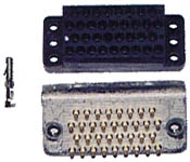 |
Many wood and composite aircraft builders will use a bonding network that interconnects all grounds and then terminates at the engine providing a ground. It is a metallic network installed specifically to provide a ground. This helps explain the difference between bonding and grounding. The bonding network must be grounded.
The wire used for grounding must be adequate to carry the electrical load. A braided grounding strap is often used. You should also check each grounding connection with an ohmmeter. To be sure you have a good connection between two metal parts the surfaces must be completely clean. Any protective coating should be removed. This can be accomplished by sanding the surface. After the bonding connection is completed, the area can be protected using a varnish. For an excellent discussion on grounding and bonding refer to the AeroElectric Connection written by Bob Nuckolls.
INSTALL INSTRUMENTS TO MONITOR THE SYSTEM
You want to know the status of your electrical system as you operate your aircraft. Proper instrumentation can alert you of actual or potential problems. The battery ammeter is a necessary instrument. You want to know the state of your battery at all times. The ammeter indicates the amount of current flowing into or out of your battery. The instrument you install should show both charging and discharging current. You can then interpret the condition of your battery and its charging system with this instrument. After 1 hour of flying a typical battery should reach a fully charged state. The indication of this would be a slight indication on the positive side of the ammeter. The ammeter may be used to detect a number of problems. Be sure to install this instrument.
Molex pin crimping tool
Another instrument you may want is a voltmeter. This instrument will monitor the electrical system voltage. In a 14-volt electrical system, a reading of 13-15 volts would be normal. Readings less than 12 volts are usually indicative of a problem. For instance, a very low reading could mean that the battery is failing.
A warning light may also be installed as an added method of monitoring the electrical system. This can be in the form of a light used to monitor an overvoltage or under voltage condition. This could be very helpful in detecting a high voltage condition that might require shutdown of the electrical system or warn of alternator failure. An overvoltage light or a higher than normal load could also be the first warning of an impending electrical fire. The light may allow you to detect the problem before it becomes too serious.
The importance of monitoring the electrical system becomes even more critical if you are going to be flying at night or IFR. You will want to know the status of your battery, in particular. If you lose your primary source of electrical power, the alternator, you want to know that you can depend upon your battery to supply power to the essential items necessary for an immediate landing.
COMPLETE A SCHEMATIC DIAGRAM
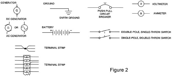
Your schematic diagram is nothing more than a road map of the electrical system. The symbols used in electrical diagrams vary from one manufacturer to another. Some of the symbols are fairly universal but you still may find differences. These symbols are actually a language of electrical components and are sometimes difficult to understand. I would not be too concerned about the symbols. More importantly, you want to map out your system very simply so you can understand it. Mapping it out allows you to trouble shoot electrical problems during installation and at a later time when you may encounter a problem. Use as many common symbols as possible so that when another person tries to find a problem at a later date they will be successful. You can indicate the length of wires along with the size on the schematic. Define each piece of electrical equipment along with part numbers if you desire. Show where bus bars and circuit breakers are in relation to the system and physically in the airplane. Several common symbols are found in Figure 2. Anything you can do to map out your system will be most helpful at a later date. Build your schematic diagram as you build your electrical system. This will be much more effective than trying to remember everything after it is installed. Build it to suit your needs but build it so that it can be understood by someone else who may be helping you with a problem or a new owner.
Hopefully, the articles presented this month and last will take some of the mystery out of electrical systems as they apply to amateur-built aircraft builders. You can certainly dig in much deeper than I have in these two articles. There are several books available that will explain in depth electricity and the installation of an electrical system. I have chosen purposely to keep this as simple as possible. I do not think you have to understand all of the intricacies of electricity to properly design and install your electrical system. Only a very basic understanding is necessary along with proper planning of the system. Planning, as always, is key during this phase of construction. Plan your electrical system early in the building process. Talk to other builders of similar type aircraft to see how they have overcome electrical problems. Attend the EAA/SportAir workshop on Electrical Wiring and Avionics. You will be given an opportunity to understand and actually practice the techniques needed for your installation at this workshop. Most of all, keep it as simple as possible. Outline your system, determine wiring and circuit breaker requirements, connect everything properly, and install instruments to monitor the system. Be sure to detail a schematic diagram for future reference and problem solving.
By Ron Alexander, © 1998. The author can
be emailed directly at ralexander@sportair.com
This article was first published in EAA Sport Aviation magazine (September
1998).
The article represents the viewpoints of the author, and not necessarily those of Zenith
Aircraft Company.