AIRCRAFT CONSTRUCTION
An Article Series
by Ron Alexander
ELECTRICAL SYSTEMS SIMPLIFIED
Part 1
By Ron Alexander
Somewhere during the aircraft building process you will encounter the often-dreaded task of installing the electrical system. It is likely that you will not receive a lot of help from your plans or assembly manual. The amount of instruction varies from one airplane to another. Usually, however, you will be left to design and install an electrical system specific to your needs. The first question to ask yourself is, "Do I want an electrical system?" You may not. If you are building a very simple airplane and have no desire for a radio or a starter, then save yourself a lot of work and the airplane a lot of weight by not installing an electrical system. Most of us will want to take advantage of the benefits derived by having a starter, radios, lights, etc. Putting in your electrical system need not be a complicated process. Like everything else involved in aircraft building, you need to know a few basic concepts. This does not mean you are required to gain the knowledge necessary to become an electrical engineer. The wiring process can be as simple or as complicated as you would like to make it. As an example, the Airframe and Powerplant Mechanics General Handbook contains over 200 pages on basic electricity, generators and motors. You can spend a considerable amount of time learning about electricity. You may decide that you want to do that for your own personal satisfaction. Personally, I am not interested in learning all of the fundamentals of electricity. I am simply concerned with how to wire my airplane. The point is, if you have a longing to learn all about electricity, the information is certainly available. Many builders do.
If you are like me and want to know only the fundamentals, then read on. Understand that I am not an expert on electrical systems but I have researched the material available and I have condensed it down to what I think you need to know to properly wire your aircraft. As Tony Bingelis so aptly states in his book Sportplane Construction Techniques, wiring an aircraft involves two basic activities:
Installing the electrical equipment where it needs to be or where you want it to be.
Connecting it to a power source (battery/bus bar, etc.) using wires.
I like that. Very simple and to the point. Each component part has a power source that is connected by a wire that has only two ends. One end is connected to the piece of equipment and the other end to a power source. Is this an oversimplification? I really don't think so. Of course, there is a lot more involved in a proper electrical system installation but if we keep it in-perspective it really is not that complicated.
Proper planning of your electrical system is absolutely essential. Do not wait until you are in the middle of the building process to think about this. You will need to route electrical wiring, determine the best location for your battery, think about where to put a bus bar, etc. during the initial building stages. The basic steps involved in planning your electrical system are as follows:
- Determine what electrical equipment you want to install
- Locate these components within the aircraft structure
- Locate your battery, bus bars and circuit breaker panels
- Protect the components by determining proper wire size and circuit breaker/fuse requirements
- Connect component parts to an adequate power source
- Ground and bond necessary items
As previously stated, you should design your system to suit your needs. Are you going to fly in marginal or adverse weather (IFR)? Will you be flying at night? If so, you will want to pay close attention to preventing a system failure. You must plan your system to operate the essential equipment for the necessary period of time you will need to land the airplane. FAR Part 23, that regulates the airworthiness of production aircraft, states that essential elements must be powered by the battery for a minimum of 30 minutes. Stop and think for a minute - 30 minutes is not that long when you are operating on a standby system. It may seem like a long time but in actuality it is minimal. On the other hand, if you are simply going to fly day VFR then you are not going to install a very elaborate system. You may only need an engine starter and a radio. No matter what your choice the basics remain the same, only the complexity of installation varies.
Prior to discussing the steps of system installation outlined earlier, I will discuss the very basics of electricity and I mean very basics. There are only a few things you really need to understand to accomplish your installation. As I mentioned earlier, if you want to plunge in deeper you certainly have that opportunity.
BASIC ELECTRICITY
Let's begin with the old familiar ohm's law. This law is the
very foundation of all principals of electricity. The law itself simply shows the
relationship between electrical current flow, pressure and resistance. Current flow is
measured in amperes (amps). Electrical resistance is measured in ohms. This resistance is
simply an opposition to electrical flow. The pressure of electricity is measured in volts.
One volt is the amount of electrical pressure required to push one amp of electrical flow
through one ohm of resistance. Or another way of stating this is to say that when you pass
one amp of current through a conducting object having a resistance of one ohm, the result
will be a voltage drop of one volt. The formula is shown in Figure
1.
E stands for voltage or pressure, R equals resistance,
and I equals current in amps.
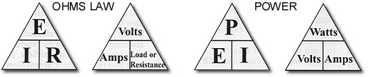
One additional formula that you will find helpful involves determining power. Power is expressed in watts and is found by multiplying the voltage times the current ... P=E x I. One volt of pressure forcing one amp of flow will produce one watt of power. A watt is a unit of energy. Concerning the chart in Figure 1, if you will place your thumb over the value you wish to calculate you will either divide the other two values or multiply as indicated. As an example, if you wish to calculate R, hold your thumb over the R and divide as indicated. The temptation is to go on with basic electricity but I will easily overcome that temptation. Knowledge of these formulas will assist you in designing your electrical system.
BATTERIES AND ALTERNATORS
Your system will undoubtedly contain a battery. We are all familiar with a battery, but what is its purpose? First and foremost it provides the necessary power to start the aircraft engine. In some aircraft that do not have an alternator or generator it may be the only source of power for all electrical items. The battery also provides electrical power in the event the generator/altemator fails. When it comes to choosing your battery you have a number of choices. Lead acid batteries are probably the most common. This type of battery has been around for years and is quite common on automobiles and aircraft.
These batteries are usually fairly inexpensive. Lead acid batteries emit explosive gases that must be vented. This will be discussed later. Another common battery is the so-called gel-cell. This is also a lead acid battery that has a material added to the electrolyte converting it into a gel state. This type of battery is less likely to spill and is often used in acrobatic aircraft. Nickel-cadmium batteries are also available. These batteries do present some maintenance problems and are not widely used on smaller aircraft. A very good choice of battery today is the recombinant gas battery (RG). They do not leak and they can be mounted in any position. The disadvantage is the price - they are usually more expensive.
Most amateur-built aircraft will require a 12-volt battery instead of a 24-volt. Most designs call for a 14-volt electrical system versus a 28-volt due largely to cost and weight differences. A 14-volt system utilizes a 12-volt battery. Even though a battery is rated at 12 volts the actual voltage will vary depending upon the charge state. Battery amperage also comes into play as we make the decision as to what type to install. Should you buy a 25 amp or 35 amp battery? Starting performance in addition to operation of essential equipment must be taken into consideration. Generally speaking, a 25 ampere-hour battery is adequate for most light aircraft. When you purchase your battery keep this thought in mind - it may be operating your emergency equipment while you shoot that low approach in bad weather after the loss of your alternator.
Alternators are simply generators that produce alternating current. They are the most common forms of electrical power on aircraft today. An alternator converts mechanical energy into electrical energy that can power our electrical components. Most alternators today are lightweight (6-8 pounds) and provide a considerable amount of amperage (typically 40 amps or more). You must calculate the needs of your entire system prior to selecting the alternator. Common ratings are 30 to 50 amps.
RELAYS, CONTACTORS AND SOLENOIDS
| A relay or contactor is usually installed to activate an engine starter. It serves to eliminate the need to run a heavy cable from the battery and starter all the way to the master switch. A contactor or relay is simply an electromagnetic switch that operates a heavy current circuit. These are often called solenoids. A large wire (usually 4 gauge) is installed between the contactor, the battery, and the starter. A smaller gauge wire (usually 18 gauge) is then run between the relay and the master switch. | 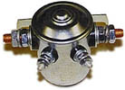 Relay |
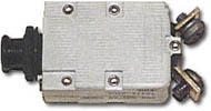
VOLTAGE REGULATORS
A voltage regulator must be present to protect the battery. The charging voltage going into the battery must be controlled within a relatively small range - as an example, 13.8-14.2 volts for a typical lead acid battery at normal temperatures. This voltage varies with the ambient temperature. The voltage regulator is going to prevent battery overcharging by decreasing the alternator output as the battery nears a full charge state. Most other equipment within your airplane can withstand a wide range of voltage. Just about any solid-state regulator will control most alternators.
| CIRCUIT PROTECTION |
|
We must protect individual electrical circuits from overloads. This is usually accomplished using a fuse or a circuit breaker. Fuses and circuit breakers are not intended to protect the equipment, rather, they are installed to protect the cable (electrical wire) attaching the power source and the equipment. Of course, in protecting the cable the equipment is also protected. Fuses will be cheaper to purchase and lighter in overall weight than circuit breakers. During flight it is easier to reset a circuit breaker than change a fuse. If you closely analyze most electrical faults they are produced by failure of an electrical device that in turn causes it to draw an extremely high amount of current. In reality, how often will you be able to solve the problem by resetting a circuit breaker or replacing a fuse? Probably not very often. A short in a wire will also cause an electrical fault.
The bottom line is that you must select the right size circuit breaker or fuse for the size wire you are running to the component part. The circuit protection should open before the wire gets hot enough to begin smoking. Another point worth mentioning is that if the circuit protection is too small for the wire size you will get a nuisance protection requiring you to reset the circuit breaker or replace the fuse even though a major problem may not exist. The following chart found in FAA Advisory Circular 4313 shows the comparison between wire size and circuit protection.
| Wire
AN Gauge Copper |
Circuit Breaker Amps |
Fuse Amps |
| 22 | 5 | 5 |
| 20 | 7.5 | 5 |
| 18 | 10 | 10 |
| 16 | 15 | 10 |
| 14 | 20 | 15 |
| 12 | 25/30 | 20 |
| 10 | 35/40 | 30 |
| 8 | 50 | 50 |
What would happen if we did not comply with these guidelines? Let's assume we install a 10-amp circuit breaker in a circuit connected by a 22 gauge wire. As long as everything is normal you will probably not know the difference. However, should an electrical fault occur in this circuit, the breaker may not trip until the wire gets so hot that it causes an electrical fire.
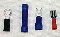
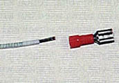
ELECTRICAL WIRING AND CONNECTORS