In this month's column, in
contrast to our last column in the December '85 issue
of LIGHT PLANE WORLD, we will discuss the structural
standpoints of the raw materials of which our
aircraft are built. This viewpoint is quite different
from the supply possibilities, and also the ease
and safety of use (our own health as well as the
aircraft’s structural integrity).
One important word of caution, before we begin, to the
"would-be designer" - the technical data presented
here are typical values which are very adequate
to compare materials, but are not the guaranteed
values which must be used in structural analysis.
(See ANC-18 for wood, and MIL-HDBK-5 and other
handbooks for metals, the manufacturer's
specifications for fibers, resins and their proven
combinations). Special tests are required for new
combinations and special "unconventional" applications.
Designing a new aircraft, or redesigning (modifying) an existing design, should be done by the amateur builder only with the help of a reputable light aircraft designer. The following situations are to be avoided: 1) too heavy a structure and, 2) not a strong enough airframe. Anyone who has been around amateur builders and designers long enough has seen them tapping on their wings or fuselage and saying, "That's strong enough", but is it really?
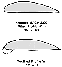 At low speed and high load factors, say a 75
degree bank and a speed just over 2.5 times the stall speed,
the aerodynamic load is inclined some 20 to 30 degrees
forward. Will this wing which may even have been "sand
bag tested" in the "normal" load condition
stand it? Or will the wing, which has been improved from a
NACA 23012 profile by adding the "STOL" nose cuff
to improve its original abrupt stall characteristics (because
not correctly twisted), stand up to the new torsional loads
due to a four-fold increase in the twisting moment
coefficient (cm from -.008 to -18)?
At low speed and high load factors, say a 75
degree bank and a speed just over 2.5 times the stall speed,
the aerodynamic load is inclined some 20 to 30 degrees
forward. Will this wing which may even have been "sand
bag tested" in the "normal" load condition
stand it? Or will the wing, which has been improved from a
NACA 23012 profile by adding the "STOL" nose cuff
to improve its original abrupt stall characteristics (because
not correctly twisted), stand up to the new torsional loads
due to a four-fold increase in the twisting moment
coefficient (cm from -.008 to -18)?
Such loads are usually associated with an increase in cruise speed, say from 130 mph to 150 mph, by increasing the original design horsepower from 100 bhp to 150 bhp. This will further increase the torsion load on the wing by a factor of (150/130)2. Will your "new" wing stand those loads? If you are not sure, you better ask somebody who really knows.
We will discuss the above formulas within the course of this series, but for this month's column, we will stick strictly to a comparison of materials. The values themselves should not be used as design data.
The focus of our article this month is our Table which gives typical values for a variety of raw materials.
Column 1 lists the standard materials which are easily available at a reasonable cost. As this column is not intended to be an "academic lecture," we will not discuss "fantastic" materials because we cannot afford them anyway. We want to acquire a simple, good understanding of practical solutions and practical materials.
Some of the materials that fall along the borderline between practical and impractical are:
- Magnesium: An expensive material. Castings are the only readily available forms. Special precaution must be taken when machining magnesium because this metal burns when hot.
- Titanium: A very expensive material. Very tough and difficult to machine.
- Carbon Fibers: Still very expensive materials.
- Kevlar Fibers: Very expensive and also critical to work with because it is hard to "soak" in the resin. When this technique is mastered, the resulting structure is very strong, but it also lacks in stiffness.
The values given in our Table are for fiberglass with polyester resins, which is very easy to use compared to the more critical (viscous) epoxy fiberglass. Epoxy fiberglass provides a somewhat stiffer and stronger result. ("Prepreg," epoxy pre-impregnated cloth, is still very expensive, has a limited shelf life and needs pressure as well as an oven to cure).
Aluminum Alloy 7075 - "T-whatever", has been left out intentionally as it is a very strong but also very brittle alloy. It is comparable to glass. Unless we state a "life" for a specified part made of 7075, it is unsafe to use this alloy in most light aircraft. (We are not an airline with an on-going maintenance schedule - we want to fly our planes year after year without having to worry about fatigue of our aircraft structure, something we'll talk about later.)
Columns 2 through 6:
Columns 2 through 6 list the relevant material properties
in metric units. The multiplying factor on the bottom line
will transform the figures into North American Units.
Column 2, the density (d), is the weight divided by the volume.
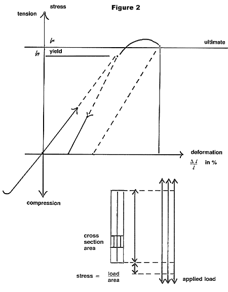
Column 3, the yield stress (fy), is the stress (load per area) at which there will be a permanent deformation after unloading (the material has yielded, given way ... ).
Note to Table: The units used are the usual Metric S.I. (or MKFS) international technical system where kg f = kg force (not mass as in the Metric MKS, used in physics.) The usual North American units and the conversion factors are also supplied in the bottom lines.
Column 4, the ultimate stress (fu), is the stress (load per area) at which it cannot carry a further load increase. It is the maximum load before failure.
Column 5, the elongation at ultimate stress (e), in percentage gives an indication of the 'Toughness" of the material.
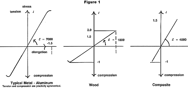
Column 6 lists the Yongs Modular or Modulus of Elasticity (E), which is the steepness of the stress/strain diagram as shown in Figure 1.
Important Note: For wood, the tension is much greater (2 to 3 times) than the compression. Both values are given in the Table. For fiberglass, the same applies, but the yield is so dependent on the manufacturing process that we cannot even give 'Iypical values'.
Both wood and fiberglass need special analysis procedures to predict the strength of a specific structural member. This analysis is quite different from classic strength of material formulas. Today we have to warn the "I wood' be designer" that his off-the-shelf computer program may be okay for metal, but not for wood and composites, even with the so-called "averaging" factors. We will not discuss further here, but the serious student may want a comprehensive textbook for engineers - not technicians who do not have enough mathematical background. (STRENGTH OF MATERIALS by Timoshenko, is a recommended sourcebook - Timoshenko, STRENGTH OF MATERIALS, Part 1, 1955, "Elementary Theory and Problems", $24.95; Part 11, 1956, "Advanced Theory and Problems", $31.50. Available from Krueger Publishing Company, P.O. Box 9542, Melbourne, FL 32902-9542.)
You see, math formulas and computers are tools like, say, a planer. if you know how to set them, where and how to use them, you can do very well with them. But if you play the sorcerer's apprentice, it becomes dangerous for the tool, the operator and the material.
Columns 7 to 10: Columns 7 to 10 are values which allow the comparison of materials from a weight standpoint (the above referenced text by Timoshenko will also show you why we use those "funny" looking values).
Column 7 gives the stiffness of a sandwich construction. The higher the value, the stiffer the construction. From the Table, we see that metals are high wood comes close, but fiberglass is low: which means fiberglass will be heavier for the same stiffness.
Column 8 shows the column buckling resistance for the same geometric shapes. This time, wood is better than the light alloys, coming before steel and fiberglass. (Surprisingly, the usual welded steel tube fuselage is not very weight efficient.)
Column 9 gives the plate buckling stiffness, which is also a shear strength measure. Here again, wood (plywood) is in a very good position before aluminum and fiberglass, with steel not very good.
Column 10 provides a crude way of measuring the strength to weight ratio of materials because it does not take into account the various ways the material is used in "light structures". According to this primitive way of looking, unidirectional fibers are very good, followed by high strength (2024) aluminum and wood, then the more common aluminum alloys and finally steel.
From just this simple table, we find there is not one material that provides an overwhelming solution to all the factors that must be considered in designing a light aircraft. Each material has some advantage somewhere. The designer's choice (no preconceived idea) will make a good aircraft structure ... if the choice is good!
This article is presented as part of a series, where aeronautical engineer Chris Heintz discusses the technical aspects of his light aircraft designs in laymen terms.
This article was published in EAA Light Plane World magazine (March 1986). © 1986, Chris Heintz.
[Back] [Chris Heintz Design College]
|
Zenith Aircraft
Company |
© Zenith Aircraft Company: 2006-03-30